External Sensor Integration and Operation
In addition to the built-in sensors such as GNSS, additional external sensors can be integrated to measure physical or environmental parameters and transmit the data to the FOSSA Nexus.
FOSSA Nexus incorporates two external connectors designed to interface with any external sensor provided by the user. These connectors support the following communication interfaces:
- I2C
- Half-duplex RS-485
- 1-Wire
- UART
- 2 × 4–20 mA sensor inputs
Additionally, they include:
- 2 × Digital input/output (GPIO)
- 3 × Analog inputs (ADC)
Connector Specifications
- Socket P/N (FOSSA Nexus side): MOLEX 532611271
- Connector P/N: MOLEX 510211200
Note: Connectors are available upon request.
| Available connector pins upon request | |||
|---|---|---|---|
| Pin name | Pin type | Pin description | |
| GND | Power | Ground | |
| RS485_P | RS485 | RS485 positive data line | |
| RS485_N | RS485 | RS485 negative data line | |
| SDA | I2C | I2C data line | |
| SCL | I2C | I2C clock line | |
| 3,3V | Power | 3,3V output, max 1A combined | |
| 5V | Power | 5V output, max 1A combined | |
| 1-Wire | 1-Wire | 1-Wire data line | |
| DIG1 | Digital | Digital Input/Output 1 | |
| AIN1 | Analog | Analog signal input (single-ended), max 500Hz | |
| 4-20 Sensor_1 | 4-20 | 4-20 data line | |
| 4-20 Sensor_2 | 4-20 | 4-20 data line | |
| AIN2 | Analog | Analog signal input (single-ended), max 500Hz | |
| Tx | UART | UART transmission line | |
| Rx | UART | UART reception line | |
| 5V | Power | 5V output, max 1A combined | |
| 3,3V | Power | 3,3V output, max 1A combined | |
| DIG2 | Digital | Digital Input/Output 1 | |
| AIN3 | Analog | Analog signal input (single-ended), max 500Hz | |
| RS485_N | RS485 | RS485 negative data line | |
| RS485_P | RS485 | RS485 positive data line | |
The following sections describe how to integrate different types of external devices with the FOSSA Nexus.
Inter-Integrated Circuit (I2C)
The FOSSA Nexus provides one I2C interface, which can be configured either as controller (master) or Peripheral (slave), depending on the host system requirements. The user must determine the appropriate configuration based on their application. The following configurations are available:
FOSSA Nexus as Controller (Master)
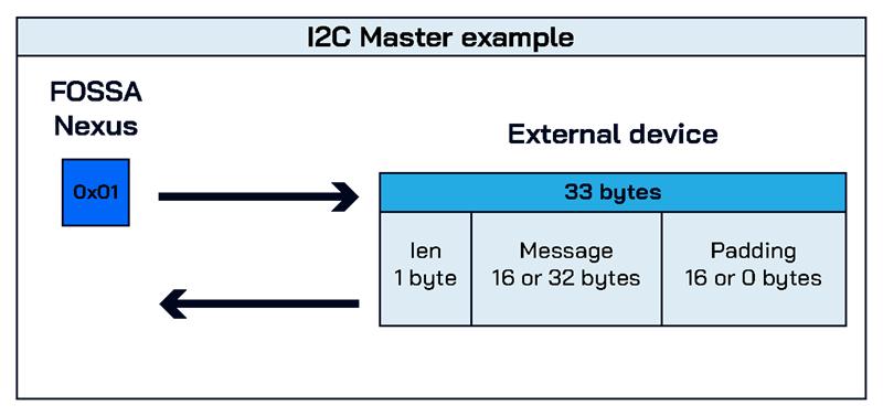
In this mode, FOSSA Nexus periodically requests data from the connected sensor. The polling period must be defined by the user. The following figure illustrates an example of this configuration:
FOSSA Nexus as Peripheral (Slave):
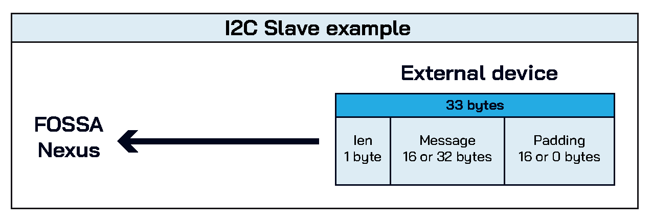
In this mode, FOSSA Nexus prepares and maintains updated data for external access. This interface is not continuously available; access windows must be coordinated with FOSSA Systems during deployment.
FOSSA Nexus as Controller (Master) + GPIO Trigger
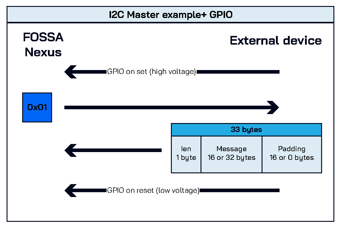
This configuration combines I2C Controler/Master mode with a GPIO input trigger. FOSSA Nexus requests data only when the GPIO signal is set, allowing for event-driven data acquisition.
This method is more efficient than periodic polling or passive response, and successfully covers most use cases. The following figure illustrates an example of this setup.
FOSSA Nexus as Peripheral (Slave) + GPIO Trigger
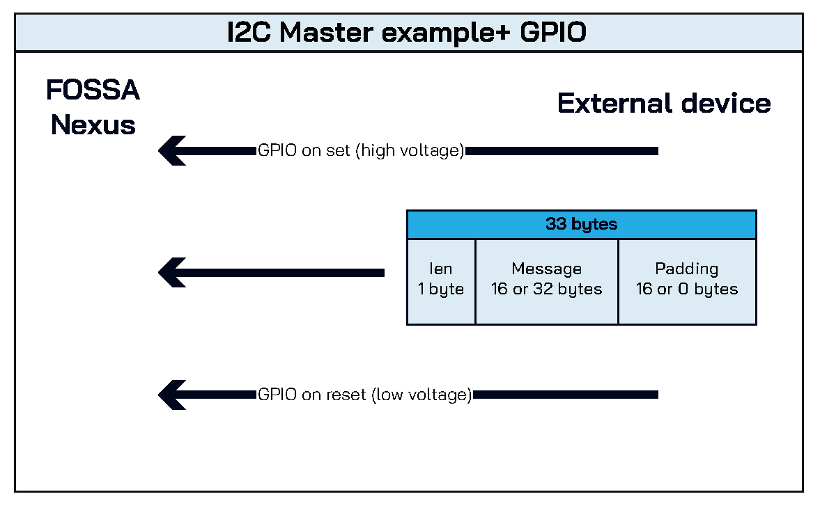
In this mode, FOSSA Nexus prepares data only when the GPIO signal is set, allowing external systems to retrieve updated information during specific events.
This configuration is efficient for data handling and is suitable for most integration scenarios. The following figure shows an example of this setup.
I2C Interface – Integration Examples
-
Monitoring periodic data
A sensor device calculates environmental parameters from a tree and keeps its data updated. FOSSA Nexus, acting as master, periodically commands the device to respond with the latest measurements. -
Triggering alarms
In setups where immediate response is needed, a GPIO input is used to signal the FOSSA Nexus. Once the GPIO is set, FOSSA Nexus issues an I2C command to retrieve alarm-related data from the external device.
4-20 mA sensors
The FOSSA Nexus supports two 4–20 mA sensor inputs, which can be read directly from its software. This interface is suitable for analog sensors that output current proportional to a physical measurement (e.g., pressure, temperature, pH).
Before integration, it’s necessary to define how the data will be framed and interpreted. This configuration must be agreed upon with FOSSA Systems.
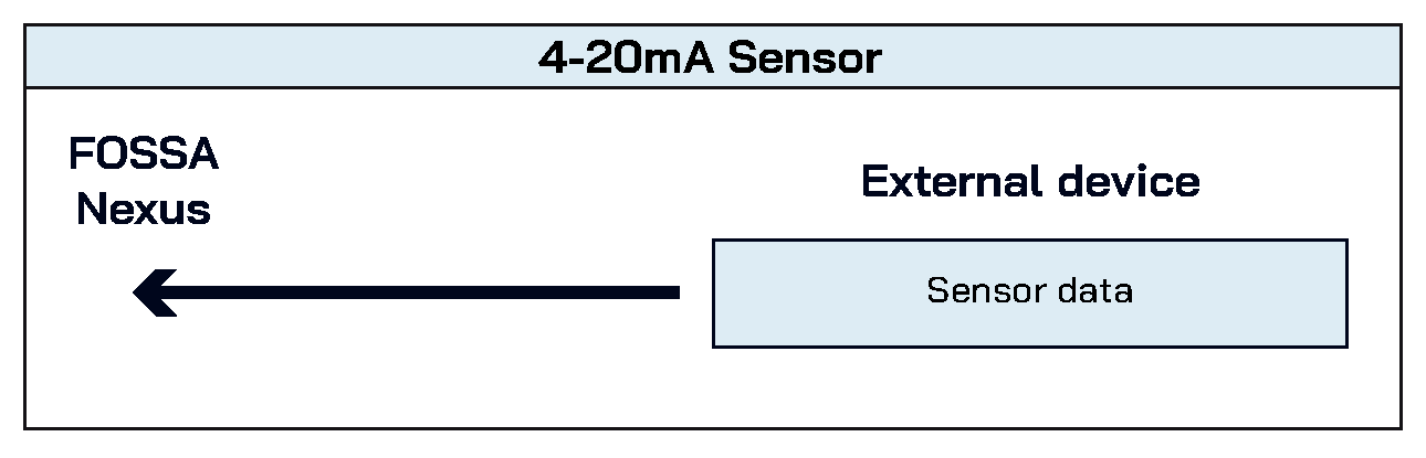
- Periodic Measurement
FOSSA Nexus reads sensor data at regular intervals. The measurement period must be defined during setup. This mode is ideal for continuous monitoring applications.
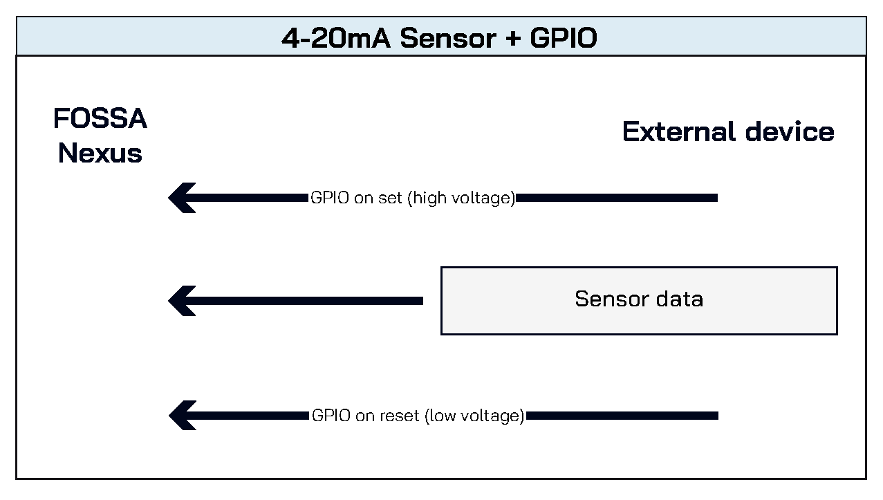
- GPIO-Triggered Measurement
FOSSA Nexus reads sensor data only when a GPIO input is activated. This mode is efficient for event-driven measurements or threshold-based alerts.
Integration Examples
-
Monitoring periodic data
For example, measuring the pH level of a lake used for agriculture. FOSSA Nexus reads the sensor at defined intervals to track environmental conditions. -
Level triggering
If the water level in a tank drops below a predefined threshold, a GPIO signal is activated. FOSSA Nexus then reads the current level via the 4–20 mA sensor and communicates the result.
Analog-Digital Converter (ADC)
The FOSSA Nexus includes three ADC interfaces, which can be read directly from its software. Each ADC instance can alternatively be configured as a GPIO interface if required.
This interface supports two modes of operation, similar to the 4–20 mA sensor inputs. Data framing must be defined in coordination with FOSSA Systems.
- Periodic measurement: FOSSA Nexus reads analog values at regular intervals. The measurement period must be specified during setup.
- GPIO-triggered measurement: FOSSA Nexus reads analog values only when a GPIO input is activated.
The same examples described for 4–20 mA sensors apply to ADC interfaces.
General Purpose Input/Output (GPIO)
FOSSA Nexus provides two GPIO interfaces, which can be configured as either digital inputs or outputs depending on integration needs.
GPIOs are typically used as triggers to initiate specific actions within the FOSSA Nexus.
For example: activating an alarm when a specific condition is detected.
RS485
FOSSA Nexus includes one RS485 interface, operating in half-duplex mode. It can be configured to either retrieve data from an external device or passively receive data. The configuration must be defined during integration.
Available Configurations
-
FOSSA Nexus listening only
FOSSA Nexus listens for incoming packets of 16 or 32 bytes at predefined intervals. These listening periods must be coordinated during setup. -
FOSSA Nexus retrieving data
FOSSA Nexus actively communicates with the external device at selected intervals. To enable this mode, a valid frame structure must be provided so the external device can respond with the appropriate data. -
FOSSA Nexus listening only + GPIO input
Similar to the listening-only mode, but instead of fixed intervals, FOSSA Nexus activates listening when a GPIO signal is set.
The same examples described for the I2C interface apply to RS485 configurations.
One-Wire
The One-Wire interface functions similarly to I2C, but uses a single wire for communication with the external device. FOSSA Nexus includes one One-Wire interface.
Available Configurations
-
FOSSA Nexus as coordinator (master)
FOSSA Nexus requests data from the external device at defined intervals. -
FOSSA Nexus as Peripheral (slave) FOSSA Nexus prepares and maintains updated data for external access.
-
FOSSA Nexus as coordinator (master) + GPIO input
FOSSA Nexus requests data only when a GPIO signal is set.
The same examples described for the I2C interface apply to One-Wire configurations.
UART Interface
The UART interface is accessible via the USB-C port on the FOSSA Nexus. It requires the following configuration:
- Baud rate: 115200 bps
- Data format: 8 bits per word, no parity bit, one stop bit
Depending on the connected device, a driver installation may be necessary to enable communication.
This interface allows direct message transmission to the FOSSA Nexus. Incoming messages are stored immediately upon reception. Accepted message sizes are 16 bytes and 32 bytes, composed of standard ASCII characters (e.g., those typed from a PC keyboard).
After sending the message, the transmitting device must append either a carriage return (\r) or a line feed (\n) character. These are typically sent by pressing the Enter key.
⚠ Warning: The UART interface is only available when the FOSSA Nexus is not connected to the Solar Panel Accessory or the power grid.
Wi-Fi Interface
FOSSA Nexus integrates Wi-Fi capabilities that allow external devices to communicate with its internal HTTP server. When properly connected, a client device can send messages to the FOSSA Nexus central database using an HTTP POST request.
Required Parameters
- URL:
http://192.168.4.1/link/msg - Payload:
{"cmd":"11223344556677889900112233445566"}
The payload must be a JSON-formatted message. The value of thecmdattribute is a hexadecimal string where each pair of characters represents one byte. Accepted message sizes are: - 16 bytes → 32 hexadecimal characters
-
32 bytes → 64 hexadecimal characters
-
Headers:
{"content-type": "application/json"}
This header specifies the format expected by the FOSSA Nexus HTTP server.
LoRa Interface
FOSSA Nexus integrates LoRa communication capabilities, allowing it to listen for packets using specific modulation parameters. These parameters are defined in coordination with FOSSA Systems and can be adjusted according to integration requirements.
The LoRa interface becomes active when Gateway Mode is enabled. This mode is configured on demand by FOSSA.
Once enabled, the protocol and listening intervals will be tailored by FOSSA for each specific device integration, ensuring optimal performance for every application. If a packet is received by the FOSSA Nexus and its size is either 16 bytes or 32 bytes, the FOSSA Nexus stores the data in memory for later transmission via satellite.
Example Modulation Parameters
- Frequency: 865.3 MHz
- Spreading Factor: 9
- Bandwidth: 125 kHz
- Coding Rate: 4/8
- LoRa Sync Word: 0x12
- Preamble Length: 8
- LDRO: Off